Address:
Plot No. B-6/5, Site 5 Surajpur Industrial Area, Block F, Surajpur Site V, Greater Noida, Uttar Pradesh 201306
For Business: +91 9212314779
For Careers: +91 84483 40400
Landline: 0120-4298000
Address:
Plot No. B-6/5, Site 5 Surajpur Industrial Area, Block F, Surajpur Site V, Greater Noida, Uttar Pradesh 201306
For Business: +91 9212314779
For Careers: +91 84483 40400
Landline: 0120-4298000


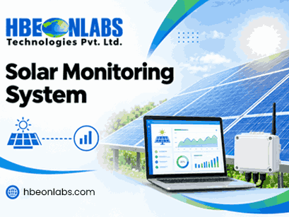
The role of a solar monitoring system is changing as distributed rooftop solar deployments become more connected, data-driven and centrally managed. For installations participating in the PM Surya Ghar: Muft Bijli Yojana ecosystem, simply collecting inverter parameters is no longer an adequate way to think about monitoring architecture.
A modern monitoring setup needs to address communication reliability, device identification, data integrity, remote diagnostics, secure transmission, centralised connectivity and long-term operational visibility. MNRE has published compliance requirements for inverters and communication devices used under PM Surya Ghar and has also issued draft guidelines concerning RMS for inverter communication devices, dongles and data loggers connected to a centralised platform.
This changes the engineering question. Instead of asking whether an inverter data logger can read voltage, current and energy values, solar companies need to assess whether the complete monitoring architecture can acquire, validate, transmit, store and manage the required data reliably at scale.
An inverter data logger performs an important function. It acquires information from the inverter through available communication interfaces and makes that information available to a monitoring platform.
Typical inverter parameters can include:
However, collecting these parameters does not automatically create an effective Solar Monitoring System.
The difference lies in what happens before and after the data reaches the logger.
A field device may successfully read an inverter but still fail to provide dependable monitoring if the communication link is unstable, timestamps are incorrect, records are lost during network outages, device credentials are duplicated, or the cloud platform receives incomplete or invalid values.
A production-grade system therefore needs several interconnected layers:
Inverter → Local communication interface → Data logger/gateway → Connectivity layer → Secure transmission → Centralised platform → Analytics and alerts
Each layer has a different engineering responsibility.
The first requirement is dependable communication between the inverter and the monitoring device.
Many solar monitoring system installations rely on interfaces such as RS485 and protocols such as Modbus. The challenge is not merely establishing a connection. The monitoring device needs to handle communication timing, register mapping, response validation, retries, timeout conditions and inverter-specific variations.
A multi-vendor deployment makes this more complex. Different inverter manufacturers can expose different register structures, parameter names, scaling factors and communication behaviours.
A robust data logger should therefore have a well-defined device abstraction layer. This allows inverter-specific mappings to be managed without redesigning the entire monitoring architecture.
For system integrators, this is particularly important when the same monitoring platform needs to support several inverter models.
Raw telemetry should not automatically be forwarded to the server.
A monitoring device should be capable of identifying obvious data anomalies before transmission. Examples include impossible values, sudden discontinuities, invalid register responses and missing readings.
Consider a situation where an inverter suddenly reports zero generation. The monitoring platform needs to distinguish between:
Without local validation and appropriate status information, all six conditions can appear similar at the application layer.
This is why a capable inverter data logger should communicate not only equipment values but also the health of the data acquisition process itself.
Network availability cannot be assumed across every rooftop installation.
A 4G connection may temporarily become unavailable. A Wi-Fi network can fail. SIM authentication can stop working. A server may become unreachable. During these periods, the monitoring device should not simply discard the measurements.
Local storage with store-and-forward capability provides a mechanism for retaining records until communication is restored.
A robust architecture should maintain:
This becomes increasingly important when monitoring thousands of distributed installations. Even short communication interruptions can create significant data gaps when multiplied across a large deployment.
MNRE’s published RMS material has also addressed local storage, transmission intervals and mechanisms for retrieving stored records, demonstrating why data persistence is an important part of remote monitoring architecture.
A PM Surya Ghar-ready architecture needs more than an internet connection.
Communication devices become part of an operational technology environment. They transmit equipment data, device identifiers and operational information to remote systems. Security therefore needs to be considered at both device and communication levels.
Depending on the deployment architecture, the monitoring device may require:
Two-way communication requires particular care. If the monitoring architecture supports remote configuration or commands, authentication and authorisation become as important as data encryption.
A device that can transmit data securely but accepts unauthorised configuration changes is not adequately protected.
For large-scale rooftop deployments, connectivity needs to be managed as an operational component rather than treated as a simple SIM card requirement.
M2M connectivity can provide a structured approach to managing connected devices deployed across multiple locations. The monitoring architecture should account for SIM provisioning, network availability, device identification and connectivity status.
The hardware also needs to handle poor signal conditions without creating unnecessary data loss.
A cellular monitoring device should ideally be able to detect communication status, retain data locally and resume transmission when connectivity returns.
This is particularly relevant to a 4G LTE solar data logger deployed across geographically distributed installations.
Time synchronisation is an underestimated part of solar monitoring.
When measurements from thousands of installations are collected centrally, every record needs a dependable timestamp. Incorrect time information can affect daily energy calculations, event correlation, performance analysis and troubleshooting.
Device identity is equally important.
Each monitoring unit should have a unique and traceable identity associated with the relevant installation and equipment. A centralised platform should be able to determine:
Previous MNRE remote monitoring material has identified practical issues such as duplicated device identifiers, incorrect location data, connectivity failures and erroneous data transmission as causes of monitoring problems.
A Solar Monitoring System should monitor the monitoring device itself.
This distinction is critical.
An inverter can be operating normally while its data logger is offline. Conversely, the logger can remain connected while the inverter has stopped communicating.
A mature monitoring architecture should therefore track parameters such as:
This creates a separate device-health layer that allows operators to identify whether the problem originates in the generation asset, the communication interface or the monitoring infrastructure.
A PM Surya Ghar-ready monitoring architecture should be designed with centralised data handling in mind.
A central platform can aggregate information from distributed systems and provide a common environment for asset visibility, reporting, fault monitoring and data management.
The architecture should therefore support structured data models rather than simply forwarding raw inverter registers.
For example, a central system may need to associate:
Site → Plant → Inverter → Monitoring Device → Parameter → Timestamp → Value → Status
This structure makes the data usable for analytics and operational workflows.
It also provides a foundation for integrating monitoring information with enterprise systems, maintenance platforms and other energy-management applications.
Energy generation is only one performance indicator.
IEC 61724-1:2021 defines terminology, equipment and methods for photovoltaic system performance monitoring and analysis. The standard also covers monitoring system choices and has been updated to address areas including bifacial systems, irradiance measurement and soiling measurement.
A technically capable monitoring architecture can therefore extend beyond basic inverter telemetry.
Depending on the system design, useful data can include:
This allows operators to investigate why a plant is underperforming rather than simply observing that energy production has fallen.
Basic monitoring platforms often generate alerts whenever a value crosses a predefined threshold.
That approach can produce excessive notifications.
A better architecture combines equipment data with operational context.
For example, low power generation during a period of low irradiance should not necessarily produce the same alert as low generation during strong solar conditions.
Similarly, an inverter reporting zero output while the monitoring device has also lost communication should be classified differently from an inverter that is online and explicitly reporting a shutdown condition.
Contextual alerting requires the monitoring platform to understand the relationship between:
Equipment state + communication state + environmental conditions + historical behaviour
This creates more useful information for service teams and reduces unnecessary field inspections.
Large-scale deployments make manual device servicing expensive.
A monitoring device deployed across hundreds or thousands of sites should therefore be designed with lifecycle management in mind.
Depending on the product architecture, this may include:
Any remote update mechanism must be designed with strong security controls and recovery mechanisms. An unsuccessful firmware update should not leave a monitoring device permanently inaccessible.
The software architecture cannot compensate for unsuitable field hardware.
Solar monitoring devices are commonly installed near electrical equipment and may experience temperature variation, dust, moisture, electrical noise and unstable power conditions.
Hardware design therefore needs to consider:
For example, a monitoring device installed in a rooftop environment requires different engineering considerations from a laboratory IoT gateway.
The same principle applies to related solar electronics. A charge controller for solar panels has a different functional role from an inverter communication device, but both need to be designed around the electrical and environmental conditions of solar installations. Confusing the two can result in inappropriate system architecture.
A monitoring system that works for 20 installations may not work efficiently for 20,000.
Scaling introduces new challenges in:
The device architecture and cloud architecture therefore need to be considered together.
A scalable Solar Monitoring System should make it possible to add new devices without manually rebuilding the communication architecture for every installation.
Before selecting a monitoring solution, solar companies should assess the complete technical chain rather than evaluating the data logger in isolation.
Key questions include:
| Evaluation area | What to examine |
| Inverter communication | Supported interfaces, protocols and vendor mappings |
| Data acquisition | Sampling, validation and error handling |
| Local storage | Data retention and recovery after outages |
| Connectivity | 4G, Wi-Fi or other supported communication methods |
| Security | Authentication, encryption and access control |
| Device identity | Unique identification and installation mapping |
| Central platform | Data ingestion, APIs and asset management |
| Diagnostics | Device and inverter health information |
| Firmware | Version control and update mechanisms |
| Scalability | Ability to support distributed deployments |
| Analytics | Performance, alarms and historical data |
| Compliance | Alignment with applicable MNRE requirements |
The objective should not be to find a device that simply reads inverter registers. The objective is to establish a dependable communication and monitoring infrastructure that can operate throughout the lifecycle of the solar installation.
At HBeonLabs Technologies Pvt. Ltd., we approach solar monitoring from the electronics and IoT engineering side. Our capabilities cover embedded technology, electronics design, IoT application development, communication interfaces and electronics manufacturing. For solar applications, our focus is on developing connected hardware that can acquire field data, communicate through suitable interfaces and connectivity technologies, and support remote monitoring requirements. Our Hbeon-DLWU provides Wi-Fi connectivity with RS485, RS232, TTL and USB interfaces, while the Hbeon-DL4GU uses 4G LTE Cat 1 connectivity with two-way communication. We can work across hardware, embedded software and connected application requirements so that the monitoring device is considered as part of the complete system rather than as an isolated inverter accessory.
A PM Surya Ghar-ready monitoring architecture needs to go well beyond basic inverter data logging.
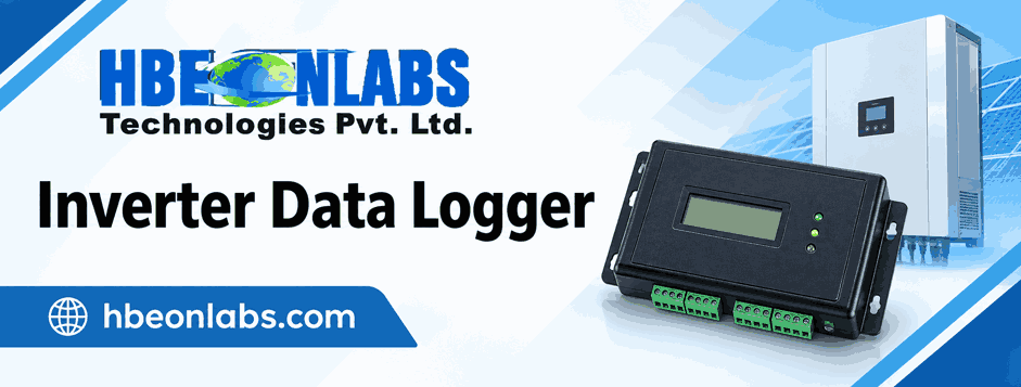
The inverter data logger remains an important component, but it is only the field acquisition layer. A dependable Solar Monitoring System also needs reliable inverter communication, local data validation, store-and-forward storage, secure connectivity, accurate timestamps, unique device identity, device health monitoring and centralised data integration.
For large distributed rooftop deployments, scalability and lifecycle management become equally important. Remote diagnostics, structured alerts, firmware management and performance analytics can further improve the operational value of the monitoring infrastructure.
The central engineering principle is simple: solar monitoring should be designed as an end-to-end communication and data system. When the hardware, embedded software, connectivity, security and central platform are designed together, the resulting architecture is better positioned to support the technical and operational requirements associated with India’s expanding rooftop solar ecosystem.
1. What makes a Solar Monitoring System PM Surya Ghar-ready?
It should support applicable MNRE communication and monitoring requirements, including reliable inverter communication, secure data transmission, device identification and centralised connectivity.
2. Is an inverter data logger enough for rooftop solar monitoring?
Not by itself. A complete system also requires reliable connectivity, local data storage, device health monitoring, secure transmission and centralised data management.
3. Why is store-and-forward important in solar data loggers?
It retains data during network or server outages and transmits stored records once connectivity is restored, reducing monitoring gaps.
4. What role does 4G play in solar monitoring?
4G enables remote data transmission from distributed solar installations without depending on local Wi-Fi, while supporting continuous connectivity monitoring.
5. What should companies consider when selecting a solar monitoring device?
Consider inverter compatibility, communication interfaces, connectivity, data storage, security, remote diagnostics, scalability and applicable MNRE requirements.