Address:
Plot No. B-6/5, Site 5 Surajpur Industrial Area, Block F, Surajpur Site V, Greater Noida, Uttar Pradesh 201306
For Business: +91 9212314779
For Careers: +91 84483 40400
Landline: 0120-4298000
Address:
Plot No. B-6/5, Site 5 Surajpur Industrial Area, Block F, Surajpur Site V, Greater Noida, Uttar Pradesh 201306
For Business: +91 9212314779
For Careers: +91 84483 40400
Landline: 0120-4298000


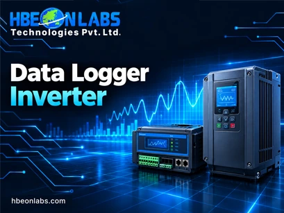
Solar inverter data logger compatibility is an important engineering consideration for inverter manufacturers, solar equipment suppliers, and system integrators managing installations across different inverter models. A data logger inverter solution must communicate reliably with each supported model and retrieve accurate operating parameters, even when the devices use different protocols, register maps, or firmware versions.
These differences can affect energy reporting, fault monitoring, remote diagnostics, and integration with a remote monitoring system (RMS). For solar inverter OEMs and technology providers, compatibility must be established through documented interfaces and structured testing rather than connector matching alone. Understanding these technical requirements helps manufacturers reduce integration errors, improve monitoring reliability, and validate data logger performance before deploying it across multiple inverter models.
A solar inverter converts the direct current produced by photovoltaic modules into alternating current for use or export. It also generates operational information, including voltage, current, power output, energy production, temperature, and fault status.
An inverter data logger collects this information and transfers it to a monitoring platform or another authorised destination. Depending on the device design, it may communicate with the inverter through RS485, RS232, TTL, USB, or a supported wireless interface. Cellular or Wi-Fi connectivity can then provide the link to the monitoring infrastructure.
The difficulty arises when a solar equipment provider works with several inverter models or manufacturers. One inverter may expose its operating parameters through Modbus RTU, while another uses a proprietary serial protocol. Even when two inverters support Modbus, their register addresses, scaling factors, function codes, and supported data points may differ.
A compatible solution must therefore address three separate requirements:
Failure at any of these levels can lead to missing readings, incorrect energy values, repeated communication errors, or incomplete monitoring records.
The first step in integration is identifying the communication interface supported by each inverter model. However, selecting the correct interface is only the starting point.
RS485 is widely used in industrial equipment because its differential signalling supports communication over relatively long cable runs and performs well in electrically noisy environments when the installation is designed correctly.
Many inverters use RS485 for Modbus RTU or manufacturer-specific communication. Integration teams must verify the terminal assignments, polarity, baud rate, data bits, parity, stop bits, device address, and termination requirements.
A reversed A/B connection, incorrect serial configuration, unsuitable termination, or poor cable routing can prevent communication even when the logger and inverter nominally support the same protocol.
RS232 is generally used for point-to-point serial communication. Some inverter designs and service interfaces use it for configuration, diagnostics, or data access.
Engineers must verify the signal voltage levels, transmit and receive connections, grounding arrangement, and connector pinout. RS232 and RS485 are electrically different, so they cannot be connected directly without appropriate interface hardware.
TTL serial interfaces are found in embedded electronics and internal communication headers. The signal voltage may be 3.3 V, 5 V, or another level specified by the equipment manufacturer.
Connecting a logger with incompatible voltage levels can damage the interface or produce unreliable communication. Teams should confirm whether the inverter exposes a supported external interface or an internal engineering port before designing the connection.
USB may support service access, data transfer, or a specific device communication function. Its presence does not automatically mean that the inverter provides a documented monitoring protocol over USB.
Similarly, Wi-Fi and Bluetooth availability does not guarantee access to operational data. Some implementations support commissioning only, while others provide local monitoring or access through a proprietary application.
The integration specification should identify the exact function supported by each interface, not simply list the connector type.
Protocol integration becomes more complex when a data logger inverter solution must support multiple manufacturers or product generations.
Modbus RTU is a common example. It defines a communication method, but it does not establish a universal register map for every solar inverter. Manufacturers can assign different addresses to power, voltage, current, energy, temperature, and fault information.
Consider two hypothetical inverter models:
| Parameter | Inverter Model A | Inverter Model B |
| Communication protocol | Modbus RTU | Modbus RTU |
| Output power register | 1000 | 3001 |
| Power scaling | 0.1 W per unit | 1 W per unit |
| Energy representation | 32-bit unsigned | 32-bit unsigned |
| Byte order | Manufacturer-defined | Manufacturer-defined |
These values are illustrative, not actual specifications. They demonstrate why a logger cannot assume that identical protocol names mean identical data structures.
If the logger reads the wrong register or applies the wrong scaling factor, the resulting data may be incorrect even though every communication request succeeds.
A reliable integration process should verify the following:
For proprietary protocols, the team may also need message-format documentation, command definitions, checksums, and manufacturer-approved access methods.
A compatibility matrix is one of the most useful tools for managing a mixed inverter portfolio. It records the exact combinations of hardware, firmware, communication settings, and data points that have been verified.
A practical matrix should include:
| Validation field | Information to record |
| Inverter identification | Manufacturer, model, hardware revision |
| Firmware | Version tested and known limitations |
| Physical interface | RS485, RS232, TTL, USB, or supported wireless interface |
| Protocol | Modbus RTU or documented proprietary protocol |
| Serial configuration | Baud rate, parity, data bits, stop bits |
| Device addressing | Supported address range and configuration method |
| Parameter mapping | Register, data type, scaling factor, engineering unit |
| Data availability | Supported, unsupported, or conditional parameters |
| Test status | Passed, failed, or awaiting validation |
| Known limitations | Firmware restrictions, unsupported functions, special settings |
This matrix should be maintained as a controlled engineering document. A firmware update can change communication behaviour, while a new inverter revision may use different register definitions despite retaining the same product name.
A compatibility claim should identify the tested model and relevant firmware version wherever possible. Broad statements such as “works with all solar inverters” are difficult to substantiate without extensive, documented testing.
For manufacturers that need to support several inverter families, the logger’s software architecture is as important as its communication hardware.
A scalable design separates communication handling from inverter-specific data interpretation. This allows engineers to add support for new models without rewriting the entire monitoring application.
A practical architecture may contain four layers.
Communication layer: Handles the physical interface, serial configuration, message transmission, response timeouts, and communication errors.
Protocol driver layer: Implements the relevant protocol, including request construction, response parsing, addressing, and checksum or integrity checks where applicable.
Device profile layer: Stores inverter-specific register maps, scaling factors, supported parameters, firmware restrictions, and polling requirements.
Data processing layer: Converts raw readings into standard engineering units, validates values, assigns timestamps, and prepares records for transmission to the monitoring platform.
This separation reduces duplicated code and makes troubleshooting more precise. If communication succeeds but power readings are incorrect, engineers can investigate the device profile or data-processing layer rather than assuming that the hardware has failed.
For larger deployments, device profiles should be version-controlled and tested before release. Configuration changes should also be traceable so that support teams can identify which mapping was active when a particular reading was recorded.
Even a correctly implemented protocol can produce unreliable results if the polling strategy does not match the inverter’s capabilities.
A data logger typically requests multiple parameters at regular intervals. Polling too frequently can overload the communication bus, increase response timeouts, or interfere with other devices sharing the same connection.
Engineers should determine:
Where multiple inverters share an RS485 bus, each device must have an appropriate address, and the network topology must follow the equipment and interface specifications. Duplicate addresses can cause response collisions and unreliable readings.
Polling schedules should also account for parameters that change at different rates. Fast-changing power values may need more frequent sampling than cumulative energy or configuration information.
The logger should distinguish between a valid zero reading and missing data. For example, zero power at night may be normal, while zero power caused by a communication timeout must not be recorded as a genuine measurement.
Solar installations can experience network interruptions, electrical noise, inverter restarts, and temporary server unavailability. A robust data logger must handle these events without corrupting the monitoring record.
At the inverter interface, the logger should use suitable response timeouts, bounded retries, error counters, and communication status indicators. Repeated failures should be recorded with enough diagnostic information to identify the affected device and time period.
For cloud transmission, a store-and-forward mechanism can retain records locally during an internet outage and transmit them after connectivity returns, provided the logger has sufficient storage and the application supports backfilling.
Data integrity also requires careful handling of timestamps, duplicate records, counter resets, and cumulative energy values. If records are retransmitted after an outage, the receiving platform should be able to identify duplicates rather than counting the same generation data twice.
Where inverter clocks and logger clocks differ, the system should define a consistent timestamp policy. Time-zone handling and daylight-saving transitions should also be considered when data is aggregated across different regions.
Testing should include realistic failure scenarios, such as disconnecting the serial cable, interrupting network access, restarting the inverter, filling the local buffer, and restoring communication after an extended outage.
Compatibility should be demonstrated through a repeatable test plan rather than a successful first connection.
A useful validation process includes the following stages.
Stage 1: Documentation review
Obtain the inverter’s communication manual, register map, electrical interface specification, supported firmware versions, and any manufacturer-specific integration instructions.
Stage 2: Bench testing
Connect the logger to each target inverter model under controlled conditions. Verify the serial configuration, device addressing, communication stability, and response handling.
Stage 3: Parameter validation
Compare logger readings against the inverter display, service software, or another trusted reference. Check scaling factors, units, signs, cumulative counters, and unavailable parameters.
Stage 4: Stress and recovery testing
Run repeated polling cycles and test communication interruptions, inverter restarts, malformed responses, and network outages. Confirm that the logger recovers without requiring unnecessary manual intervention.
Stage 5: Field validation
Test representative installations under actual operating conditions. Check cable routing, signal quality, network coverage, environmental exposure, and monitoring-platform consistency.
Stage 6: Release control
Document the tested models, firmware versions, approved configuration, known limitations, and software release. Retest affected combinations when firmware, hardware, or register mappings change.
The acceptance criteria should be defined before testing begins. They may cover communication success rate, data accuracy, recovery time, missing-record limits, and supported parameter coverage, depending on the project requirements.
Inverter compatibility should be considered early in product development, particularly when the data logger is intended for OEM supply or integration across multiple product lines.
Manufacturers should provide stable communication documentation, identify changes between firmware versions, and clarify which parameters are available to external monitoring devices. Early access to representative hardware can reduce development delays and expose protocol differences before production.
A charge controller for solar panels serves a different function from an inverter, but it can also produce operating data that a wider solar monitoring system may need to collect. Integrating charge controllers, inverters, meters, and other equipment requires a separate assessment of each device’s interface and protocol. A logger designed for inverter communication should not be assumed to support a charge controller without verification.
The same principle applies to national or utility monitoring platforms. Successful communication with an inverter does not automatically establish compliance with external reporting requirements. Data format, reporting frequency, connectivity, security, and acceptance testing must be assessed against the applicable specifications.
At HBeonLabs Technologies Pvt. Ltd., we develop electronics, embedded systems, and IoT solutions for businesses that require dependable device communication and remote monitoring. Our data logger portfolio includes Wi-Fi and 4G connectivity options, with interfaces such as RS485, RS232, USB, and TTL, subject to the specifications of the relevant model. We work with customers to assess integration requirements, evaluate communication interfaces, and identify the testing needed for their target inverter models. Our approach focuses on practical compatibility, reliable data transmission, and monitoring requirements so that solar equipment manufacturers can make informed decisions before deployment. For projects involving multiple inverter models, we recommend defining the supported device list and validating each model against its communication documentation before confirming compatibility.
Solar inverter data logger compatibility depends on more than a matching connector or a shared protocol name. Physical interfaces, register maps, firmware behaviour, polling schedules, data interpretation, and recovery mechanisms all affect the reliability of an integrated monitoring solution.
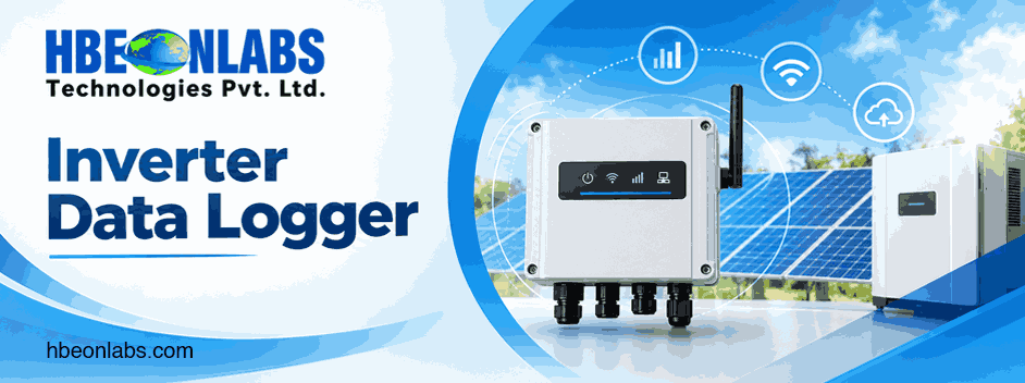
For solar inverter OEMs and system integrators, the most effective approach is to document each target model, maintain a controlled compatibility matrix, validate critical parameters against trusted references, and test failure recovery before production deployment.
A well-designed inverter data logger can support a wider range of equipment when its communication architecture is modular and its device profiles are properly validated. By treating compatibility as an engineering process rather than a marketing claim, manufacturers can reduce integration risk, improve monitoring reliability, and establish a clearer path from prototype testing to large-scale deployment.
Check the inverter’s communication interface, supported protocol, register map, serial settings, and firmware version. Test the data logger against each target model to verify parameter accuracy, communication stability, and error recovery before deployment.
Yes, a single data logger can support multiple inverter brands if it has the necessary protocol drivers, device-specific register mappings, and configuration options. However, compatibility must be verified for each inverter model and relevant firmware version.
Solar inverter data loggers commonly use Modbus RTU over RS485, while some inverter models use RS232, TTL serial communication, or proprietary protocols. The supported protocol depends on the inverter’s hardware and firmware specifications.
Common causes include incorrect serial settings, mismatched register addresses, incompatible electrical interfaces, duplicate device addresses, wiring errors, electrical interference, and unsupported firmware versions. Systematic testing helps identify the source of the failure.
Manufacturers should evaluate interface compatibility, protocol support, data accuracy, firmware adaptability, connectivity options, local data buffering, remote monitoring integration, and technical support. Testing the logger with the intended inverter models helps establish its suitability for production deployment.