Address:
Plot No. B-6/5, Site 5 Surajpur Industrial Area, Block F, Surajpur Site V, Greater Noida, Uttar Pradesh 201306
For Business: +91 9212314779
For Careers: +91 84483 40400
Landline: 0120-4298000
Address:
Plot No. B-6/5, Site 5 Surajpur Industrial Area, Block F, Surajpur Site V, Greater Noida, Uttar Pradesh 201306
For Business: +91 9212314779
For Careers: +91 84483 40400
Landline: 0120-4298000


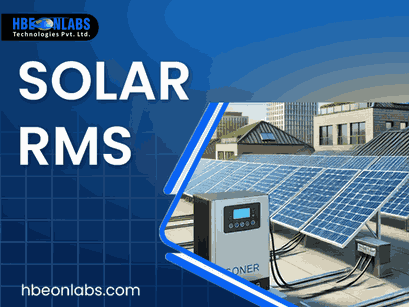
A Solar RMS depends on reliable communication between the inverter, data logger and monitoring platform. The communication interface used at the inverter level directly affects how consistently operating data can be collected, transmitted and processed.
For solar inverter manufacturers, EPC companies, system integrators and businesses developing monitoring equipment, choosing between RS485, RS232 and TTL is not simply a matter of selecting a commonly used interface. The right choice depends on the inverter architecture, communication protocol, cable distance, electrical environment, number of connected devices and the design of the Solar Data Logger.
RS485 is widely used in solar applications because it supports longer communication distances and multiple devices on the same bus. RS232 remains useful for point-to-point communication, while TTL is generally suited to short-distance communication within electronic equipment.
Understanding these differences before designing or integrating a solar power data logger can prevent communication failures and unnecessary hardware changes during deployment.
A communication interface provides the physical connection through which an inverter exchanges data with a Solar RMS or data logging device.
The interface itself does not necessarily define what the transmitted information means. For example, parameters such as voltage, current, power generation, energy consumption, fault codes and inverter status are generally governed by a communication protocol such as Modbus. The physical interface determines how those digital signals travel between the devices.
A typical Solar RMS architecture can include:
Solar inverter → Communication interface → Solar Data Logger → Internet connectivity → Cloud platform → Monitoring dashboard
The data logger collects information from the inverter and transfers it to the monitoring system. Depending on the product architecture, the logger may use RS485, RS232 or TTL on the inverter side and Wi-Fi, 4G or another network connection for cloud communication.
Therefore, selecting the interface requires consideration of both the inverter’s hardware and the requirements of the complete monitoring system.
RS485 is often the most practical interface for industrial and solar monitoring applications where communication must work reliably over longer cable runs.
Unlike a typical point-to-point interface, RS485 can support communication across a bus, allowing multiple devices to share the same communication network when the protocol and network design support it.
Longer communication distance
RS485 is designed for communication over considerably longer distances than TTL. This makes it suitable for solar installations where the inverter and data logger may not be positioned directly next to each other.
Better noise immunity
Solar installations contain switching equipment, power electronics, cables and other sources of electrical interference. RS485 uses differential signalling, which provides better resistance to common-mode electrical noise compared with single-ended interfaces.
Multi-device communication
RS485 can support multi-drop configurations. This can be useful when several inverters need to communicate through a common communication network, subject to the protocol, addressing and hardware implementation.
Industrial suitability
The interface is widely used in industrial automation and equipment monitoring. Its characteristics make it suitable for applications where reliability is more important than a simple short-distance connection.
Many solar inverter communication systems use Modbus over RS485. In such a configuration, the physical layer is RS485 while Modbus defines how information is structured and exchanged.
For a Solar Data Logger, this means the hardware must support the required electrical interface as well as the inverter’s communication protocol and register mapping.
An integration team should therefore confirm:
Simply providing an RS485 port does not guarantee compatibility with an inverter.
RS485 is generally a strong choice when the Solar RMS installation involves:
For many inverter monitoring applications, RS485 provides a practical balance between communication reliability, installation flexibility and hardware complexity.
RS232 is another established serial communication interface. Unlike RS485, it is primarily designed for point-to-point communication.
This means an RS232 connection normally links one transmitter and one receiver rather than providing the shared bus architecture commonly associated with RS485.
For Solar RMS integration, RS232 can be appropriate when the inverter or controller already provides an RS232 communication port and the data logger is designed to communicate through it.
Simple point-to-point communication
When only two devices need to communicate, RS232 can provide a straightforward connection.
Widely established technology
RS232 has been used across industrial, computer and embedded systems for decades. Existing equipment may therefore already include an RS232 interface.
Useful for specific equipment architectures
Some inverters, controllers, meters and industrial devices may provide RS232 as their available serial communication interface. In such cases, using RS232 can be more practical than introducing an additional conversion stage.
RS232 is less suitable than RS485 for applications requiring longer communication distances or multiple devices on the same communication bus.
It is also more sensitive to the limitations associated with single-ended signalling. For installations where several inverters need to communicate with one monitoring device, RS485 is generally more suitable if the inverter architecture supports it.
RS232 can still be a useful option for a solar power data logger when the equipment being monitored specifically requires it.
Consider RS232 when:
The key consideration is not whether RS232 is newer or older than another interface. It is whether the interface matches the equipment and installation requirements.
TTL is different from RS485 and RS232 because it generally refers to digital signal voltage levels rather than a long-distance industrial communication standard.
TTL-level serial communication is commonly found inside embedded electronic equipment. It can be useful when the inverter’s internal controller exposes serial communication directly at TTL levels.
For example, an OEM developing a custom Solar RMS solution may integrate a data logger directly with an inverter control board through a TTL interface.
Simple embedded integration
TTL can be convenient when communication occurs between components located within the same electronic assembly.
Low hardware complexity
For short-distance communication between compatible electronic circuits, TTL can avoid the additional interface circuitry required by differential communication systems.
Useful for custom electronics
OEMs developing their own inverter or monitoring hardware may use TTL at the board level where the physical design permits it.
TTL is generally not intended for long cable runs between separate pieces of equipment. Its single-ended signalling makes it more vulnerable to electrical noise, voltage differences and signal degradation over distance.
This makes TTL less suitable for direct communication across a large solar installation.
If TTL is used in a Solar Data Logger, the physical location of the logger and inverter becomes an important design consideration. Signal voltage levels must also be matched correctly. Connecting incompatible voltage levels can result in unreliable communication or hardware damage.
| Feature | RS485 | RS232 | TTL |
| Typical application | Industrial communication | Point-to-point communication | Embedded board-level communication |
| Communication type | Differential | Single-ended | Single-ended |
| Multiple devices | Supported in suitable bus configurations | Generally no | Generally no |
| Long-distance suitability | High | Limited | Low |
| Noise resistance | High | Moderate to low | Low |
| Solar plant suitability | Excellent for many installations | Application dependent | Mainly short-distance integration |
| Common use | Inverter and industrial equipment | Controllers and legacy equipment | Internal electronics and custom boards |
| Hardware complexity | Moderate | Low to moderate | Low |
| Typical integration consideration | Bus design and termination | Point-to-point connection | Voltage level compatibility |
The table provides a general comparison. Actual performance depends on the hardware implementation, communication protocol, cable quality, installation conditions and system architecture.
The correct interface should be selected after examining the complete application rather than choosing one based solely on popularity.
Start with the inverter’s technical documentation. Identify whether the available port is RS485, RS232, TTL or another interface.
If an inverter provides RS485 with Modbus RTU, a Solar Data Logger designed for that combination can normally be integrated without adding an unnecessary interface conversion.
Distance is a major consideration.
For communication between an inverter and a nearby embedded controller, TTL may be adequate. The point-to-point equipment connections over a limited distance, RS232 may work well. For longer connections across an installation, RS485 is generally more appropriate.
If one data logger needs to communicate with multiple inverters, the communication architecture needs careful consideration.
RS485 is particularly useful in multi-device environments because it supports bus-based configurations. Each inverter can be addressed through the applicable communication protocol.
Solar installations contain power conversion equipment that can introduce electrical noise. Cable routing, grounding, shielding, termination and communication speed all affect the reliability of serial communication.
For this reason, RS485 is often preferred for industrial solar installations where noise immunity is important.
The interface and protocol must be treated as separate elements.
For example, an inverter may use Modbus RTU over RS485. Another device may use a proprietary protocol over RS232. A TTL connection may also carry a specific serial protocol.
The data logger must understand the actual communication protocol, not just the physical interface.
An interface that works for a prototype may not be suitable when the same design is deployed across hundreds or thousands of installations.
OEMs should consider installation distance, inverter variants, environmental conditions, service requirements and future firmware updates before finalising the communication architecture.
A monitoring platform is only as useful as the data reaching it.
If communication repeatedly drops, the monitoring system may show incomplete production information, delayed fault notifications or missing inverter parameters. For O&M teams, this can make it harder to identify problems and evaluate system performance.
A reliable data logger should therefore do more than read inverter registers. Depending on the application, it may need features such as data buffering, breakpoint resumption, remote diagnostics, configurable transmission intervals and secure cloud communication.
For example, a solar power data logger deployed at a remote site may temporarily lose network connectivity. Local data handling and recovery mechanisms can help prevent gaps when the network becomes available again.
Solis inverters and other inverter platforms may use defined communication interfaces and protocols for external monitoring. When integrating a Solis data logger or a third-party logger with a particular inverter model, the installer or OEM should verify the exact communication specifications rather than assuming that all models use the same configuration.
The relevant parameters can include the communication port, protocol, baud rate, parity, device address and register mapping.
This is particularly important when developing a Solar RMS solution intended to support multiple inverter models. The data logger may require firmware or protocol configuration for each supported inverter family.
The communication interface should be considered alongside the data logger’s complete feature set.
For an OEM or system integrator, important evaluation points include:
This approach helps ensure that the selected Solar RMS hardware can support the intended application rather than solving only the initial communication requirement.
At HBeonLabs Technologies Pvt. Ltd., we develop electronics, embedded systems and IoT solutions for applications that require reliable data acquisition and connected monitoring. Our Solar RMS solutions include data logger hardware with interfaces such as RS485, RS232, TTL and USB, allowing integration requirements to be addressed according to the inverter and system architecture. Our Hbeon-DLWU supports Wi-Fi connectivity, while the Hbeon-DL4GU provides 4G LTE connectivity for applications requiring cellular communication. We also support features such as configurable data intervals, data recovery, remote monitoring and cloud integration. Our approach is focused on understanding the equipment, communication requirements and deployment conditions before selecting the appropriate hardware and connectivity architecture.
RS485, RS232 and TTL each have a place in Solar RMS integration, but they are designed for different communication environments.
RS485 is generally the stronger option for longer-distance industrial communication, multi-device networks and solar installations where electrical noise can be a concern. RS232 is useful for point-to-point communication where the inverter or controller already provides the interface. TTL is better suited to short-distance, board-level communication within compatible embedded systems.
For solar inverter manufacturers and system integrators, the decision should ultimately be based on the inverter’s communication architecture, protocol, installation distance, number of devices, electrical environment and future deployment requirements.
Selecting the correct interface at the design stage can improve communication reliability and simplify the development of a scalable Solar RMS solution. A properly matched Solar Data Logger then becomes an important link between inverter-level data and the monitoring platform used by engineering, operations and maintenance teams.