Address:
Plot No. B-6/5, Site 5 Surajpur Industrial Area, Block F, Surajpur Site V, Greater Noida, Uttar Pradesh 201306
For Business: +91 9212314779
For Careers: +91 84483 40400
Landline: 0120-4298000
Address:
Plot No. B-6/5, Site 5 Surajpur Industrial Area, Block F, Surajpur Site V, Greater Noida, Uttar Pradesh 201306
For Business: +91 9212314779
For Careers: +91 84483 40400
Landline: 0120-4298000


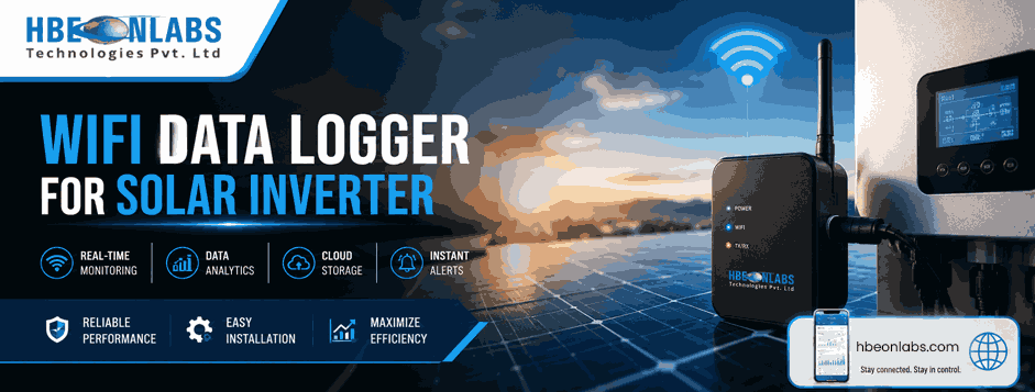
A solar inverter data logger must do more than collect readings and send them to a monitoring platform. It must maintain reliable communication, handle network interruptions, recover from firmware faults and protect stored data during long periods of operation. These requirements become more important in rooftop solar installations, where equipment may operate for years with limited physical access. For inverter manufacturers, solar equipment suppliers and system integrators, a wifi data logger for solar inverter applications must be designed around real field conditions.
Wi-Fi signal strength can vary, routers may restart, internet connections can fail, and power fluctuations can interrupt communication. A device that works well during laboratory testing may still lose data or require manual intervention after months of deployment.
Reliable performance depends on three key engineering areas: reconnection logic, watchdog mechanisms and long-term reliability testing. These functions should be planned during hardware and firmware development, rather than added after field failures occur.
A solar inverter data logger collects operating parameters such as voltage, current, power, energy generation, temperature and fault codes, depending on the inverter protocol and available registers. It then transfers this information to a monitoring server, local gateway or cloud platform.
The logger depends on several components working together:
A failure in one layer should not unnecessarily stop the others. For example, losing Wi-Fi should not prevent the logger from continuing to collect inverter readings. Similarly, a server timeout should not cause the firmware to repeatedly restart the entire device.
This separation of functions is central to a reliable data logger inverter design.
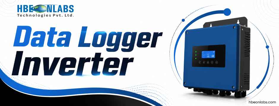
Wi-Fi disconnections can occur because of router reboots, weak signals, channel interference, password changes, access point replacement or temporary internet outages. Firmware should identify the type of failure and respond with a controlled recovery process.
Instead of placing repeated connection attempts inside the main program loop, engineers should implement a defined state machine. Typical states include:
Each state should have a timeout, an exit condition and a defined recovery action. If authentication fails, for example, the logger should not restart continuously as though the router has become temporarily unavailable. It should retain the configuration, record the error and retry according to a controlled policy.
The state machine should also distinguish between Wi-Fi association and internet availability. A logger may be connected to a router while the router itself has no internet access. Checking only the Wi-Fi connection status will not identify this condition.
Repeatedly attempting to reconnect at very short intervals can waste power, increase processor activity and place unnecessary load on the access point. A better approach is exponential backoff, where the delay between attempts increases after consecutive failures.
For example, the logger could begin with a short retry delay and progressively increase it up to a configured maximum. The actual values should be selected through testing for the intended installation and connectivity requirements. Adding random jitter can help prevent many devices from reconnecting at precisely the same time after a common power or network outage.
A successful connection should reset the retry counter. Engineers should also provide a mechanism for faster recovery when a known network event occurs, without allowing frequent events to create an endless cycle of rapid retries.
Wi-Fi recovery should run independently of inverter polling wherever the hardware and firmware architecture permit it. If the network stack is waiting for a connection, the inverter communication task should continue collecting data at the configured interval.
This approach reduces missing readings and prevents a temporary network fault from becoming a monitoring failure. It also makes fault diagnosis easier because the logger can record whether the problem occurred in inverter communication, Wi-Fi connectivity or server communication.
Reconnection logic alone cannot prevent data loss. If the server is unavailable for several hours, the logger needs a clear policy for readings collected during that period.
A store-and-forward mechanism saves validated records locally and transmits them when connectivity returns. Each record should include a timestamp, device identifier, relevant measurement fields and, where appropriate, a sequence number or quality flag.
Engineers should define the following behaviours before deployment:
For example, a logger sampling every five minutes generates 288 records per day for one stream of readings. Actual storage needs will be higher when each record contains multiple parameters, timestamps, protocol metadata or diagnostic information. Capacity planning should account for record size, filesystem overhead and the expected duration of a network outage.
The firmware should also protect stored data against unexpected power loss. Depending on the design, this may require atomic record writes, checksums, a journalled storage approach or a recovery procedure that detects incomplete records after reboot.
A watchdog is a recovery mechanism that detects when software stops making expected progress. It is particularly important in devices intended to operate continuously without regular manual servicing.
However, a watchdog should not be treated as a substitute for correct firmware design. A system that resets every time it encounters a recoverable network problem is not reliable. Excessive resets can interrupt data collection, increase flash writes and make faults difficult to trace.
A hardware watchdog can reset the processor if firmware fails to refresh it within a defined period. This is useful when the main execution path becomes stuck because of a deadlock, an unresponsive peripheral or an unexpected software fault.
The timeout should be longer than legitimate processing delays but short enough to restore service within the required recovery time. Engineers should test the watchdog by deliberately creating controlled fault conditions, rather than assuming that its presence guarantees recovery.
In a multitasking firmware design, individual tasks may appear active while one important function has stopped making progress. A task-level health monitor can track the progress of functions such as:
The watchdog supervisor should assess meaningful progress, not merely whether a task is still running. For example, a communication task repeatedly executing a loop without successfully completing or timing out a transaction should not automatically be considered healthy.
After a reset, the logger should record the reset cause when the hardware permits it. Repeated resets within a defined period can trigger a recovery mode, a longer restart delay or the disabling of a faulty non-essential function.
The device should preserve its configuration and any recoverable pending records. Where suitable, engineers can store a compact fault history containing reset reasons, network errors, inverter communication timeouts and storage failures. This information helps distinguish a firmware defect from an external network or power issue.
Wi-Fi may be the most visible part of the product, but the inverter interface is equally important. A logger using RS485 and Modbus RTU must handle invalid responses, CRC errors, timeouts, unsupported registers and differences between inverter models.
Communication polling should use bounded timeouts. If an inverter does not respond, the logger should mark the reading as unavailable or invalid rather than reusing an old value without indicating its age.
Where multiple registers are required, the polling schedule should balance data freshness with bus utilisation. Excessively frequent requests may increase communication errors, while long polling intervals can delay fault detection.
The firmware should also isolate the inverter communication task from Wi-Fi and server operations. A slow cloud response must not delay RS485 polling, and a failed Modbus transaction must not trigger a full system restart unless a separately defined critical fault requires it.
For products intended to support multiple inverter brands, protocol handling should be modular. Register maps, scaling factors, data types and model-specific behaviours should be configurable and tested independently.
Firmware recovery cannot compensate for unsuitable hardware. A Wi-Fi logger used near a solar inverter must be designed for the actual power supply, electrical noise, temperature and installation conditions.
Voltage dips or brief interruptions can reset the processor, Wi-Fi module or communication interface. The power supply should be evaluated under realistic load conditions, including Wi-Fi transmission peaks and startup current.
Brownout detection should place the device in a controlled recovery state. Engineers should verify that power cycling does not corrupt configuration data or stored readings. Protection against electrical transients and correct grounding are also important, particularly where the logger connects to inverter communication lines.
The inverter enclosure, metal mounting surfaces, nearby cables and building structure can affect Wi-Fi performance. Antenna placement should be assessed in the intended installation, not only on an open laboratory bench.
Testing should cover different signal levels, interference conditions and router positions. Where installations are spread across rooftops or electrical rooms, engineers should define acceptable signal conditions and provide practical installation guidance.
Heat, dust, moisture and repeated temperature changes can affect electronic components, connectors and enclosure materials. Component selection, thermal design and enclosure protection should reflect the intended operating environment.
Engineers should also consider connector retention, cable strain, corrosion and service access. Long-term reliability depends on the complete installation, not just the circuit board.
A reliable design requires a test plan that recreates foreseeable failures. A successful demonstration on a stable office Wi-Fi network is not sufficient evidence of field readiness.
A practical validation programme should include:
| Test condition | What to verify |
| Router power cycle | Automatic reconnection without manual intervention |
| Internet unavailable, Wi-Fi connected | Local collection continues and server recovery is detected |
| Weak or fluctuating signal | Controlled retries without excessive resets |
| Incorrect Wi-Fi credentials | Clear fault reporting and safe retry behaviour |
| Server timeout | Data remains queued until successful delivery |
| Repeated inverter timeouts | Polling recovers without blocking unrelated tasks |
| Sudden power interruption | Configuration and stored records remain consistent |
| Interrupted firmware update | Device returns to a valid operating state |
| Extended continuous operation | No unexplained resets, memory leaks or progressive performance decline |
| Full local buffer | Defined overflow policy is followed and logged |
During testing, record measurable indicators such as reconnection time, percentage of successful data uploads, missing sample count, duplicate records, watchdog resets and buffer utilisation. Set acceptance limits according to the product’s intended use and service requirements.
Long-duration tests should be combined with targeted fault injection. Running a device continuously for weeks may expose memory leaks, but deliberate router cycling, server outages, malformed responses and power interruptions are more effective at verifying specific recovery paths.
Pilot deployments should then be monitored for differences between laboratory assumptions and field conditions. Firmware updates should be released through a controlled process, with version tracking, staged deployment and a recovery plan if a new release causes unexpected behaviour.
When evaluating a data logger inverter solution, manufacturers should look beyond connectivity and the initial purchase cost. A low-cost unit may require more engineering effort if it has limited protocol support, inadequate fault recovery or insufficient local storage.
The solar data logger price should be assessed alongside integration effort, expected service life, warranty, firmware support and the cost of field visits. Technical teams should also confirm the supported inverter interfaces, configurable sampling intervals, data buffering capacity, network recovery behaviour and remote diagnostic options.
For OEMs deploying large numbers of devices, consistency across production batches is equally important. A supplier should be able to explain its hardware validation process, firmware version control, product traceability and procedure for addressing reported faults.
At HBeonLabs Technologies Pvt. Ltd., we develop IoT hardware and embedded solutions for applications that require dependable device communication and remote monitoring. Our solar data logger range includes Wi-Fi and 4G connectivity options, with interfaces such as RS485, RS232, USB and TTL, depending on the model. We work with solar inverter manufacturers and system integrators to assess interface compatibility, communication protocols and integration requirements. Our approach focuses on selecting suitable hardware, establishing reliable data transfer and aligning the logger with the customer’s monitoring platform. For OEM projects, we can discuss product configuration and customisation requirements based on the inverter architecture, deployment conditions and technical specifications.
Long-term reliability in a Wi-Fi solar inverter data logger comes from coordinated hardware and firmware design. Reconnection logic must handle network failures without interrupting local data collection. Watchdogs must detect genuine software failures without creating unnecessary reset cycles. Store-and-forward mechanisms must preserve readings during outages, while inverter communication tasks should remain independent of network activity.
These functions need to be verified through repeatable tests covering power interruptions, weak Wi-Fi signals, server outages, communication errors and extended operation. By defining recovery behaviour early and measuring performance during validation, manufacturers can reduce data gaps, limit maintenance visits and build solar monitoring systems that remain dependable in the field.
1. How should a Wi-Fi data logger for a solar inverter handle network disconnections?
A Wi-Fi data logger should use a connection state machine, controlled retry intervals and automatic reconnection logic. It should continue collecting inverter readings during network outages and upload stored data once connectivity returns.
2. What is the role of a watchdog in a solar data logger?
A watchdog detects firmware failures, stalled tasks or an unresponsive processor and initiates recovery when necessary. Hardware and software watchdogs can improve reliability, provided they are configured to prevent unnecessary resets and preserve stored data.
3. How can a solar data logger prevent data loss during internet outages?
A solar data logger can use a store-and-forward mechanism to save readings in local memory while the internet is unavailable. Once connectivity is restored, it uploads pending records using timestamps, sequence numbers and server acknowledgements to manage missing or duplicate data.
4. What factors should engineers evaluate when selecting a data logger inverter solution?
Engineers should assess inverter protocol compatibility, communication interfaces, Wi-Fi performance, local storage capacity, watchdog support, firmware update mechanisms, power supply stability and environmental suitability. The solar data logger price should also be evaluated against integration costs and long-term maintenance requirements.
5. How can manufacturers test the long-term reliability of a Wi-Fi solar data logger?
Manufacturers should test router restarts, weak Wi-Fi signals, server outages, inverter communication failures, sudden power interruptions and extended continuous operation. Monitoring reconnection time, data loss, duplicate records and unexpected resets helps identify reliability issues before large-scale deployment.