Address:
Plot No. B-6/5, Site 5 Surajpur Industrial Area, Block F, Surajpur Site V, Greater Noida, Uttar Pradesh 201306
For Business: +91 9212314779
For Careers: +91 84483 40400
Landline: 0120-4298000
Address:
Plot No. B-6/5, Site 5 Surajpur Industrial Area, Block F, Surajpur Site V, Greater Noida, Uttar Pradesh 201306
For Business: +91 9212314779
For Careers: +91 84483 40400
Landline: 0120-4298000


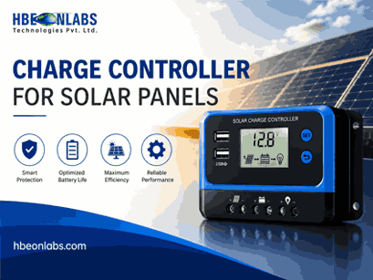
A solar charge controller does more than regulate the energy flowing from photovoltaic panels to a battery. In a connected solar system, it also needs to exchange information with inverters, battery management systems, sensors, gateways and monitoring platforms. The communication interface selected for this purpose can affect system reliability, data availability, troubleshooting, remote monitoring and future expansion.
For engineers and solar equipment manufacturers, choosing a communication protocol is therefore a system architecture decision, not simply a matter of selecting a connector.
RS485, UART, CAN and Modbus are frequently encountered in solar electronics, but they do not serve exactly the same purpose. UART is primarily a serial communication interface. RS485 defines the electrical signalling used for robust serial communication over longer distances. Modbus is a communication protocol that can operate over interfaces such as RS485. CAN is a different communication architecture designed for reliable multi-node communication and strong error handling.
Understanding these differences is important when developing or integrating a charge controller for solar panels, particularly when the controller must exchange operating data with other electronic devices.
A standalone controller can perform its basic charging function without communicating with another device. However, modern solar systems increasingly require information such as:
When this information is available through a communication interface, another controller, inverter, gateway or software platform can use it for system management.
For example, a hybrid solar system may need the charge controller and battery management system to exchange information before determining an appropriate charging strategy. Similarly, a remote monitoring platform may collect controller data through a gateway and make it available to operators.
The communication design must therefore match the electrical environment, cable length, number of connected devices, data requirements and software architecture.
RS485 is widely used in industrial and energy applications because it provides differential signalling and is suitable for communication over relatively long cable runs. Its physical layer is designed to be more resistant to electrical noise than simple single-ended serial connections.
This is particularly useful in solar installations where cables may run alongside power electronics, switching circuits and other sources of electromagnetic interference.
RS485 commonly uses a two-wire differential connection. Multiple devices can share the same communication bus when the network is designed correctly.
However, RS485 itself does not define what the transmitted data means. It is a physical communication standard. The devices still need a protocol that defines message structure, addressing, commands and data interpretation.
This distinction becomes important when evaluating equipment specifications. A product described as having an “RS485 port” does not automatically mean that it supports Modbus. The actual communication protocol must be confirmed separately.
RS485 is a strong choice when a solar controller needs:
Correct bus termination, cable selection, grounding and network topology are still essential. A technically suitable interface can become unreliable if the physical installation is poorly designed.
UART, or Universal Asynchronous Receiver-Transmitter, is a common serial communication interface used inside embedded electronics.
Unlike RS485, UART does not normally define a differential physical layer for long-distance industrial communication. It is generally used for point-to-point communication between electronic devices or within a product.
A microcontroller in a solar charge controller may use UART to communicate with another processor, a communication module, a display or a wireless modem.
UART communication typically uses separate transmit and receive signals, along with a common reference. Parameters such as baud rate, data bits, parity and stop bits must match between the communicating devices.
For product developers, UART is useful because it is simple to implement and supported by many microcontrollers. It can also provide a convenient interface between the main control board and a communication module.
However, directly extending a basic UART connection over a long cable in a solar installation is generally not equivalent to using an industrial differential interface such as RS485.
The communication requirement involves:
For an outdoor solar product, the engineer should consider the physical environment before deciding whether a UART connection is appropriate outside the enclosure.
CAN, or Controller Area Network, was developed for reliable communication between multiple electronic control units. It is particularly useful where several embedded devices need to exchange information without relying on a central host for every message.
CAN uses differential signalling and incorporates mechanisms for message arbitration, error detection and fault handling. These characteristics make it valuable in systems where communication reliability is important.
In solar energy products, CAN can be useful for communication between a charge controller, battery management system, inverter or other intelligent electronic modules.
One major difference between CAN and a simple UART connection is that CAN includes communication mechanisms at the protocol level rather than acting only as a basic serial interface.
For battery-integrated solar systems, CAN can be particularly relevant where the battery management system needs to communicate operating limits or status information to another controller.
CAN is worth considering when a system requires:
The decision should still be based on the requirements of the complete system. If an existing inverter or BMS already specifies a particular CAN communication profile, the charge controller must be designed to support the required message structure rather than simply adding a CAN transceiver.
Modbus is different from RS485 and UART because Modbus defines how devices communicate and structure their data.
A common implementation is Modbus RTU over an RS485 physical connection. In this arrangement, RS485 provides the electrical communication layer, while Modbus RTU defines how devices identify themselves, request data and respond.
For example, a monitoring gateway may request a particular register from a charge controller. The controller responds with the corresponding measurement according to the agreed Modbus register map.
This makes Modbus useful for solar applications where equipment from different manufacturers needs to exchange structured data.
However, interoperability depends on more than the word “Modbus” appearing in a datasheet. Engineers should examine:
Two devices can both support Modbus and still fail to communicate correctly if their register maps or configuration parameters are different.
These technologies should not be treated as four direct alternatives because they operate at different levels.
| Technology | Primary role | Typical solar use |
| UART | Serial interface | Internal electronics and short-distance device communication |
| RS485 | Physical signalling standard | Long-distance and multi-device wired communication |
| CAN | Robust network communication | Inverter, BMS and embedded controller integration |
| Modbus | Communication protocol | Structured data exchange, commonly over RS485 |
This distinction helps prevent a common design mistake: selecting a protocol based only on the connector or interface name.
For example, an engineer may specify RS485 when the actual requirement is “Modbus RTU over RS485”. The first describes the physical communication method, while the second describes the complete communication arrangement.
The correct approach is to start with the system requirements rather than the interface itself.
List every parameter that the charge controller needs to send or receive. Basic monitoring may require only voltage, current and energy data. A more advanced system may require fault codes, battery limits, control commands and configuration parameters.
Determine whether the controller communicates with an inverter, BMS, gateway, display, data logger or central energy management controller.
The devices already present in the system may dictate the available communication interfaces.
Short internal connections and long field connections have different requirements. A communication method suitable inside a PCB enclosure may not be appropriate for a cable running several metres through an installation.
Solar inverters and switching power electronics can create an electrically challenging environment. Differential signalling and appropriate cable installation can improve communication robustness.
Hardware alone does not provide interoperability. Firmware needs to implement the selected communication method correctly, including message handling, error conditions, timeouts and data validation.
A good communication architecture should make it possible to identify whether a problem originates from the physical connection, communication configuration, firmware or connected equipment.
This becomes especially important when a solar system is installed across many locations.
Communication becomes significantly more valuable when the controller is connected to a solar monitoring system.
A typical architecture may involve the charge controller collecting electrical measurements, an intermediate gateway or data logger receiving those values, and a cloud platform storing and presenting the information.
The data path could look like:
Charge Controller → Communication Interface → Gateway/Data Logger → Network → Cloud Platform → Monitoring Dashboard
The interface between the controller and gateway may use RS485 with Modbus RTU, UART or another supported protocol. The gateway can then use Wi-Fi, cellular connectivity or another network technology to transfer data to the monitoring platform.
This architecture separates local equipment communication from internet connectivity. It also allows the communication hardware to be designed according to the conditions at the solar installation.
A data logger becomes useful when solar equipment needs continuous data collection and remote visibility.
For example, a wifi data logger for solar inverter applications can collect operating information from compatible equipment and transfer it to a monitoring platform through a wireless network.
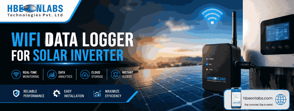
When integrating a charge controller with a data logger, engineers should verify the controller’s communication register map and data format. Parameters should also have clearly defined units and scaling.
Data logging should not be limited to successful readings. Communication failures, invalid values, missing data and equipment fault states should also be handled properly.
For large deployments, these considerations directly affect the quality of the monitoring data available to operators.
Several issues repeatedly appear during solar electronics integration.
Assuming RS485 means Modbus:
RS485 is an electrical interface. The communication protocol must be specified separately.
Using the wrong register map:
Even when both devices support Modbus, incorrect register addresses or data formats can prevent meaningful data exchange.
Ignoring termination and wiring:
Poor bus design can result in intermittent communication, especially over longer distances.
Treating communication as an afterthought:
Adding communication hardware after the main electronics design is completed can create PCB, firmware and enclosure constraints.
Not defining fault behaviour:
The system should determine what happens when communication is interrupted. Control decisions should not depend indefinitely on stale data.
Insufficient testing:
Communication should be tested under different loads, temperatures, cable conditions and operating states, not only during a bench test with ideal conditions.
For an OEM developing a solar charge controller, communication should be included in the product requirements from the beginning.
The hardware architecture needs appropriate transceivers and protection. PCB layout must account for signal integrity and electrical noise. Firmware needs communication drivers, protocol handling and fault management. The product may also require a defined register map and documentation for integration with external equipment.
Testing should cover both normal communication and failure scenarios. These can include disconnected cables, incorrect device addresses, invalid messages, communication timeouts and power interruptions.
For products intended for integration with inverters, batteries or monitoring platforms, providing clear communication documentation can significantly reduce integration effort for downstream users.
At HBeonLabs Technologies Pvt. Ltd, we work on electronics design, embedded systems, IoT and electronics manufacturing, allowing communication requirements to be considered as part of the complete product architecture. Our work can cover the development journey from electronics design and PCB development to embedded firmware, connectivity, prototyping, testing and production. We also work with data logging and remote monitoring applications, where reliable communication between field devices and monitoring platforms is essential. For solar equipment manufacturers and system developers, our approach is focused on developing electronics around the actual application, required interfaces and integration needs rather than treating communication as an isolated feature.
RS485, UART, CAN and Modbus each have a distinct role in solar electronics. UART is commonly suited to short-distance embedded communication, RS485 provides a robust physical interface for wired field communication, CAN supports reliable communication between intelligent nodes, and Modbus provides a structured method for exchanging data between compatible devices.
For a charge controller for solar panels, the right choice depends on the complete system architecture. Cable distance, electrical noise, connected devices, data requirements, firmware capability, monitoring requirements and future expansion all need to be considered.
When the controller is expected to work with an inverter, BMS, data logger or solar monitoring system, communication should be designed into the product from the beginning. A well-planned communication architecture improves integration, diagnostics and long-term system management while reducing problems during deployment.
Yes, if both devices support compatible settings and protocols, such as Modbus RTU. RS485 alone does not guarantee compatibility.
CAN is often suitable for BMS communication because it supports reliable multi-device communication and error handling. The BMS specification should determine the final choice.
It can send data through RS485, UART or CAN to a gateway or data logger, which then transfers it through Wi-Fi or cellular connectivity to the monitoring platform.
Common causes include incorrect baud rate, device address, register mapping, parity or data format. Both devices must use matching communication parameters.
Check cable distance, connected devices, required data, electrical noise, protocol compatibility, firmware requirements and communication failure handling before finalising the interface.