Address:
Plot No. B-6/5, Site 5 Surajpur Industrial Area, Block F, Surajpur Site V, Greater Noida, Uttar Pradesh 201306
For Business: +91 9212314779
For Careers: +91 84483 40400
Landline: 0120-4298000
Address:
Plot No. B-6/5, Site 5 Surajpur Industrial Area, Block F, Surajpur Site V, Greater Noida, Uttar Pradesh 201306
For Business: +91 9212314779
For Careers: +91 84483 40400
Landline: 0120-4298000


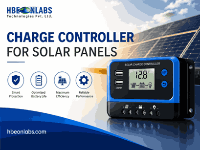
Modern solar equipment needs to do more than generate and manage electrical power. Solar charge controllers, inverters, batteries and other field devices increasingly need to exchange operating data with monitoring platforms and remote management systems. For manufacturers, this makes communication architecture an important consideration during product development and system integration.
RS485 combined with Modbus is a widely used communication approach for connecting solar equipment with external monitoring devices. When correctly implemented, it allows operating parameters from a charge controller for solar panels to be collected by a data logger, gateway or Solar Monitoring System.
However, an RS485 port alone does not guarantee compatibility. Manufacturers need to consider the physical interface, communication protocol, register mapping, addressing, data formats, wiring and testing requirements before integrating a charge controller with a monitoring architecture.
RS485 is a physical-layer communication standard designed for reliable serial communication between electronic devices. Its differential signalling makes it suitable for industrial environments where electrical noise can affect communication.
A solar installation can contain several devices that need to exchange information, including:
Using RS485 can simplify communication between these components, particularly where multiple compatible devices need to share a communication network.
For manufacturers developing a charge controller for solar panels, RS485 can provide several practical advantages:
The RS485 interface only establishes how the electrical signals are transmitted. A communication protocol is still required to define what those signals mean.
RS485 and Modbus are often mentioned together, but they are not the same technology.
RS485 is the physical communication interface. It defines the electrical characteristics used to transmit data between devices.
Modbus is the communication protocol. It defines how devices structure requests, responses, addresses and data.
A solar charge controller can therefore have an RS485 interface without necessarily supporting Modbus. Manufacturers should verify the communication protocol supported by the specific controller before connecting it to a data logger or monitoring gateway.
A common arrangement is RS485 with Modbus RTU, where the RS485 interface carries Modbus messages between the charge controller and the connected monitoring device.
This distinction matters when selecting equipment for a Solar RMS because both the physical interface and communication protocol must be compatible.
Modbus RTU is commonly used with RS485 because it provides a structured method for exchanging data between connected devices.
In a typical solar application, the charge controller acts as the slave device while a data logger, gateway or monitoring controller operates as the master.
The master sends a request for specific information, and the charge controller returns the corresponding data.
Depending on the controller, available parameters may include:
The exact parameters depend on the controller’s firmware and communication implementation.
This information can then be transmitted to a Solar Monitoring System, where operators can review system performance and identify abnormal operating conditions.
One of the most important considerations during Modbus integration is the register map.
There is no universal assumption that the same register address represents the same parameter across every solar charge controller. Each manufacturer may define its own register structure.
For example, one controller may use a particular register for battery voltage, while another may assign that parameter to a different address. The returned value may also require scaling.
A controller might return:
Battery voltage = 512
The monitoring system could need to interpret this as:
512 ÷ 10 = 51.2 V
If the scaling factor is not documented or configured correctly, the monitoring platform may display an incorrect value even though the communication itself is functioning correctly.
A proper register map should identify:
| Parameter | Register | Data Type | Scaling | Unit | Access |
| PV Voltage | Manufacturer-defined | Integer/Float | Manufacturer-defined | V | Read |
| PV Current | Manufacturer-defined | Integer/Float | Manufacturer-defined | A | Read |
| Battery Voltage | Manufacturer-defined | Integer/Float | Manufacturer-defined | V | Read |
| PV Power | Manufacturer-defined | Integer/Float | Manufacturer-defined | W | Read |
| Temperature | Manufacturer-defined | Integer | Manufacturer-defined | °C | Read |
The actual values must come from the controller manufacturer’s communication documentation.
For solar equipment manufacturers, maintaining a clear register map is essential for data logger development, monitoring integration and field support.
Even when the physical RS485 wiring is correct, communication can fail if the serial parameters are not configured correctly.
Important settings include:
For example, if the charge controller communicates at 9600 baud with 8 data bits, no parity and one stop bit, the connected monitoring device must use compatible settings.
The Modbus slave address is particularly important when several charge controllers are connected to the same RS485 network. Each device needs a unique address to prevent communication conflicts.
Manufacturers should define the default communication settings clearly and provide a method for changing the slave address where multiple devices need to operate on the same network.
Correct wiring is fundamental to reliable communication.
RS485 normally uses differential communication lines. These may be labelled A and B, although manufacturers do not always use identical naming conventions. The terminal definitions provided by the device manufacturer should therefore be followed rather than assuming that all equipment uses the same polarity convention.
The physical installation should consider:
Termination resistors may be required at appropriate points of an RS485 network, particularly in longer networks. Incorrect termination can contribute to signal reflections and communication instability.
Solar installations can also contain inverters, motors, switching devices and other equipment capable of producing electrical interference. Proper cable routing and network design can therefore have a direct effect on communication reliability.
A communication failure does not necessarily mean that the charge controller or monitoring device is defective.
Several integration problems occur repeatedly in field installations.
Reversed differential communication lines can prevent the devices from exchanging data.
A difference in baud rate, parity or stop-bit configuration can prevent communication.
Two devices using the same Modbus address can create conflicting responses.
A monitoring device may request a register that is not supported by the particular controller model.
The data may be received correctly but displayed incorrectly because the scaling factor has not been configured.
The receiving system must correctly interpret whether a register contains an unsigned integer, signed integer, 32-bit value or another data format.
Improper termination can affect signal quality and lead to intermittent communication problems.
A structured commissioning process can identify these issues before the equipment is deployed across a large number of installations.
A data logger can provide the communication bridge between a solar charge controller and a remote monitoring platform.
A typical architecture is:
Solar PV system → Charge Controller → RS485/Modbus → Data Logger → Network → Solar Monitoring System
The data logger periodically polls the charge controller for defined parameters. It then processes and transmits the collected information to a central platform.
The monitoring system can use this information to display operating values, generate reports and identify abnormal readings.
The polling interval should be selected according to the application. Excessively frequent requests can increase communication traffic, while very long intervals may reduce the usefulness of near-real-time monitoring.
For manufacturers, the data acquisition architecture should be considered during the product development stage rather than added after deployment.
Not every available parameter needs to be transmitted to the monitoring platform. Manufacturers and system integrators should identify the measurements that have practical value for monitoring and diagnostics.
Depending on the application, useful data may include:
PV-side data
Battery-side data
Load-side data
Diagnostic data
Selecting the right data points helps keep the monitoring architecture focused on parameters that support operational decisions and troubleshooting.
A Solar RMS can extend the value of RS485 and Modbus communication by making charge controller data available for centralised monitoring.
Instead of requiring technicians to visit every installation to inspect controller readings, a remote monitoring platform can provide access to collected information from multiple sites.
Depending on the system architecture, this can support:
The quality of the information available through the Solar RMS depends heavily on the underlying data acquisition process. Incorrect register mapping, scaling errors or incomplete parameter collection can reduce the usefulness of the monitoring platform.
For this reason, communication validation should be treated as part of the overall monitoring system design.
A manufacturer offering a charge controller with RS485 and Modbus support should provide sufficient technical information for external integration.
The documentation should ideally include:
This information allows OEMs, EPC companies and monitoring-system developers to integrate the controller without relying on assumptions or repeated trial and error.
Communication testing should be completed before a charge controller is released for large-scale deployment.
The testing process should include:
Testing under realistic conditions is particularly important. Laboratory communication may work correctly while field installations experience interference, longer cable runs or multiple devices on the same network.
Manufacturers should also test firmware updates to confirm that communication behaviour and register definitions remain compatible with existing monitoring systems.
Communication should be treated as part of the product specification rather than an optional addition.
Where possible, manufacturers should maintain consistent register structures and communication settings across product families. This reduces development work when an OEM or EPC company integrates multiple models.
A clear communication manual, version-controlled register map and defined testing procedure can also reduce installation and support issues.
If a firmware update changes register addresses, data formats or communication behaviour, those changes should be documented clearly. Existing Solar RMS installations may depend on the original communication structure.
Manufacturers should also distinguish between monitoring and remote control. Reading operating data through Modbus is different from allowing a remote system to change charging parameters or other controller settings.
At HbeonLabs Technologies Pvt. Ltd., we develop IoT solutions for solar equipment monitoring and communication. Our data logger solutions support interfaces including RS485, RS232, USB and TTL, allowing compatible solar equipment to connect with monitoring architectures. Our Hbeon-DLWU supports Wi-Fi connectivity, while the Hbeon-DL4GU provides GSM 4G LTE connectivity. We also provide cloud-based monitoring, real-time visibility and data transmission capabilities for solar applications. For manufacturers and system integrators, we recognise that successful integration depends on matching the data logger with the specific charge controller’s communication protocol, register structure and electrical interface. These parameters should be verified against the controller’s technical documentation before deployment.
RS485 and Modbus provide a practical way to connect a charge controller for solar panels with data loggers, gateways and a Solar Monitoring System. However, successful integration requires more than connecting an RS485 cable between two devices.
Solar equipment manufacturers need to define communication settings, Modbus addressing, register structures, data types and scaling factors clearly. Hardware considerations such as wiring, cable selection, termination and network topology are equally important.
When this communication layer is correctly designed and tested, charge controller data can be collected reliably and transferred to a Solar RMS for centralised monitoring, diagnostics and historical analysis.
For OEMs, EPC companies and system integrators, choosing equipment with well-documented communication interfaces can simplify integration, reduce commissioning problems and provide a more reliable foundation for remote solar asset monitoring.
1. Why is RS485 used with a charge controller for solar panels?
RS485 provides a reliable communication interface between a charge controller and devices such as data loggers, gateways and monitoring systems. It supports multi-device communication and is suitable for solar installations where electrical interference and longer cable runs can be concerns.
2. What is the difference between RS485 and Modbus in a solar charge controller?
RS485 defines the physical communication layer, while Modbus defines how data is exchanged between devices. A charge controller may use RS485 as its interface and Modbus RTU as the communication protocol for exchanging operating data.
3. What charge controller data can be collected by a Solar Monitoring System?
Depending on the controller, a Solar Monitoring System can collect PV voltage, PV current, PV power, battery voltage, charging current, energy generation, temperature, operating status, alarms and fault information. The available parameters depend on the controller’s Modbus register map.
4. What should manufacturers check before integrating Modbus with a solar charge controller?
Manufacturers should verify the RS485 interface, Modbus protocol, baud rate, parity, stop bits, slave address, register addresses, data types, scaling factors and read/write permissions. Correct wiring and network termination should also be tested.
5. How does a Solar RMS use RS485 and Modbus data?
A data logger can collect charge controller data through RS485 and Modbus and transmit it to a Solar RMS through an available network connection. The Solar RMS can then provide centralised monitoring, historical data, alerts and diagnostic information for connected solar installations.